Fiber Optic Splitter Types: PLC vs FBT, and 1x8 vs 1x16 vs 1x32
By Jergeo Engineering Team | Published October 2026 · 9 min read

Choosing the wrong fiber optic splitter type is one of the most common — and most expensive — mistakes in PON and FTTH design. Pick a split ratio that is too low and you waste backhaul fiber and head-end ports. Pick one that is too high and you run out of link budget, forcing costly amplifier upgrades or shorter drops than planned. Before you either waste ports or blow your power budget, this guide gives you the decision framework: the two main splitter technologies, what each split ratio really costs in insertion loss, and how to match the type to your splitting architecture.
Summary
Fiber optic splitters come in two main types: PLC (planar waveguide, best for 1x8, 1x16, 1x32 and above with stable performance) and FBT (fused taper, cheapest for low-count 1x2/1x4). Higher split ratios like 1x32 serve more subscribers but add roughly 3dB insertion loss per output doubling. Choose 1x8 for short, high-bandwidth drops; 1x16 as the balanced workhorse; and 1x32 only when your power budget and distance allow. Always verify the splitter type against your PON power budget before finalizing a design.
PLC vs FBT: the two splitter technologies
Every fiber optic splitter is fundamentally a passive device that divides one optical signal into multiple paths. But how it does that divides the industry into two types:
- PLC (Planar Lightwave Circuit) splitter: A tiny silica waveguide chip splits one input into multiple outputs on a planar substrate. Because the split happens in a precisely fabricated chip, PLC splitters deliver uniform splitting, stable performance across wavelengths, and support high split ratios (1x8 and beyond). They are the standard in modern FTTH/PON because they work bidirectionally and predictably.
- FBT (Fused Biconical Taper) splitter: Optical fibers are fused, heated, and tapered so the signal couples from one fiber into others. FBT is cheaper and fine for low-count ratios (1x2, 1x4) but becomes bulky and less uniform at high ratios, and is more sensitive to wavelength. It is a common choice for simple taps and monitor points rather than large subscriber splitting.
For any FTTH or ODN deployment that needs to serve many subscribers reliably, PLC is the type to choose. FBT has a diminishing role as networks scale — for a single 1x8, 1x16, or 1x32 requirement, PLC is the industry-standard answer because of its consistency and looser wavelength dependence.
What does 1x8, 1x16 and 1x32 actually mean?
Splitter ratios are written as in x out. A 1x8 splitter takes one input fiber and splits it into eight output fibers — feeding up to eight subscribers (or eight branch paths). The higher the number, the more users one splitter can feed, but the more the signal is divided and weakened.
The core trade-off is simple and governed by physics: every time you double the number of outputs, you lose roughly 3dB of signal. This is the "3dB per port-doubling" rule that drives every PON power budget calculation. It is why choosing the split ratio is a balancing act between subscriber coverage and reachable distance.
| Splitter Type | Typical Insertion Loss | Subscribers Served | Best For |
|---|---|---|---|
| 1x8 | 9.0 – 10.5 dB | Up to 8 | Short, high-bandwidth drops; distributed splitting |
| 1x16 | 12.0 – 13.5 dB | Up to 16 | Balanced FTTH workhorse; centralized splitting |
| 1x32 | 15.5 – 17.5 dB | Up to 32 | Max subscriber count with sufficient budget/distance |
The insertion loss values above are typical for a PLC splitter including connector loss, and always carry some excess loss on top of the theoretical 3dB-per-doubling figure. Always confirm against the actual datasheet for your splitter and connector types.
Choosing the right split ratio for your network
There is no single "best" split ratio — the right choice depends on your architecture and subscriber density, which links directly to how you deploy centralized vs distributed splitting:
- 1x8 splitter: Ideal for distributed or decentralized splitting, where you place smaller splitters closer to small groups of users (such as a small building or a sparse neighborhood). The lower insertion loss keeps signal strong for higher-speed services and longer distances from the split point. Also a good fit for high-bandwidth business drops that cannot afford 1x32's loss.
- 1x16 splitter: The balanced default most FTTH projects start with. It serves enough subscribers to be economical while keeping insertion loss moderate, making it compatible with standard GPON power budgets and typical distribution distances.
- 1x32 splitter: Maximizes subscribers served per splitter and per head-end port — the biggest lever for lowering per-subscriber cost at high density. Use it when a large number of users cluster close to the split point and your full ODN loss budget still leaves enough margin at the receiver. If distances are long or speeds are high, 1x32 may push the link beyond budget.
When you are unsure, run the power budget math: add up splitter loss, connector losses, splice losses, and fiber attenuation over your longest path, then confirm the receiver still has margin. If it does not, step down one split level (32 → 16 → 8) or move the splitter closer to users.
Where the splitter lives: cassette, tray, or module
The splitter's electrical behavior is what matters, but in ODN hardware you also choose a physical form. PLC splitters are typically packaged as cassettes (card-type units that slide into a frame, common in ODF and fiber distribution cabinets) or trays/chassis (shelf-mountable trays that hold the splitter and route pigtails). The packaging choice must match your rack, ODF, or cabinet layout — a decision covered in depth in our optical distribution frame guide and the broader FTTH network architecture guide.
Chose your split ratio first, then confirm the physical form (cassette vs tray) fits where you intend to mount it. These are separate decisions, and getting both right avoids a rework later.
A quick decision framework
- Chip technology: Choose PLC for any 1x8 / 1x16 / 1x32 FTTH need. Reserve FBT for simple low-count taps.
- Split ratio: Estimate subscribers per split point and the distance. Prefer 1x8 for short high-bandwidth drops, 1x16 as the default, 1x32 only with confirmed budget headroom.
- Form factor: Pick cassette (card) or tray/chassis based on your ODF, frame, or cabinet layout.
- Verify: Run the full ODN loss budget before finalizing — this step is non-negotiable regardless of which splitter you select.
Need the right splitter, matched to your network?
Jergeo is a factory-direct manufacturer of PLC splitter cassettes and tray chassis — including the JPLCC-8A 1x8, JPLCT-16A 1x16 and JPLCT-32A 1x32. We support SC/LC and custom connectors, OEM/ODM, MOQ from 1 unit, 1-hour response, and video inspection before shipment. Tell us your split ratio and form factor — we will match it to your ODN.
Related Products
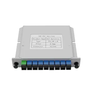
JPLCC-8A 1x8 PLC Splitter
Card-type 1x8 PLC splitter cassette for ODF and cabinet mounting
View Product →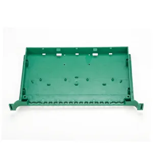
JPLCT-16A 1x16 PLC Splitter
Shelf-mountable 1x16 PLC splitter tray chassis
View Product →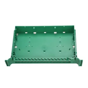
JPLCT-32A 1x32 PLC Splitter
Shelf-mountable 1x32 PLC splitter tray chassis for high-density networks
View Product →Related categories
Related Articles
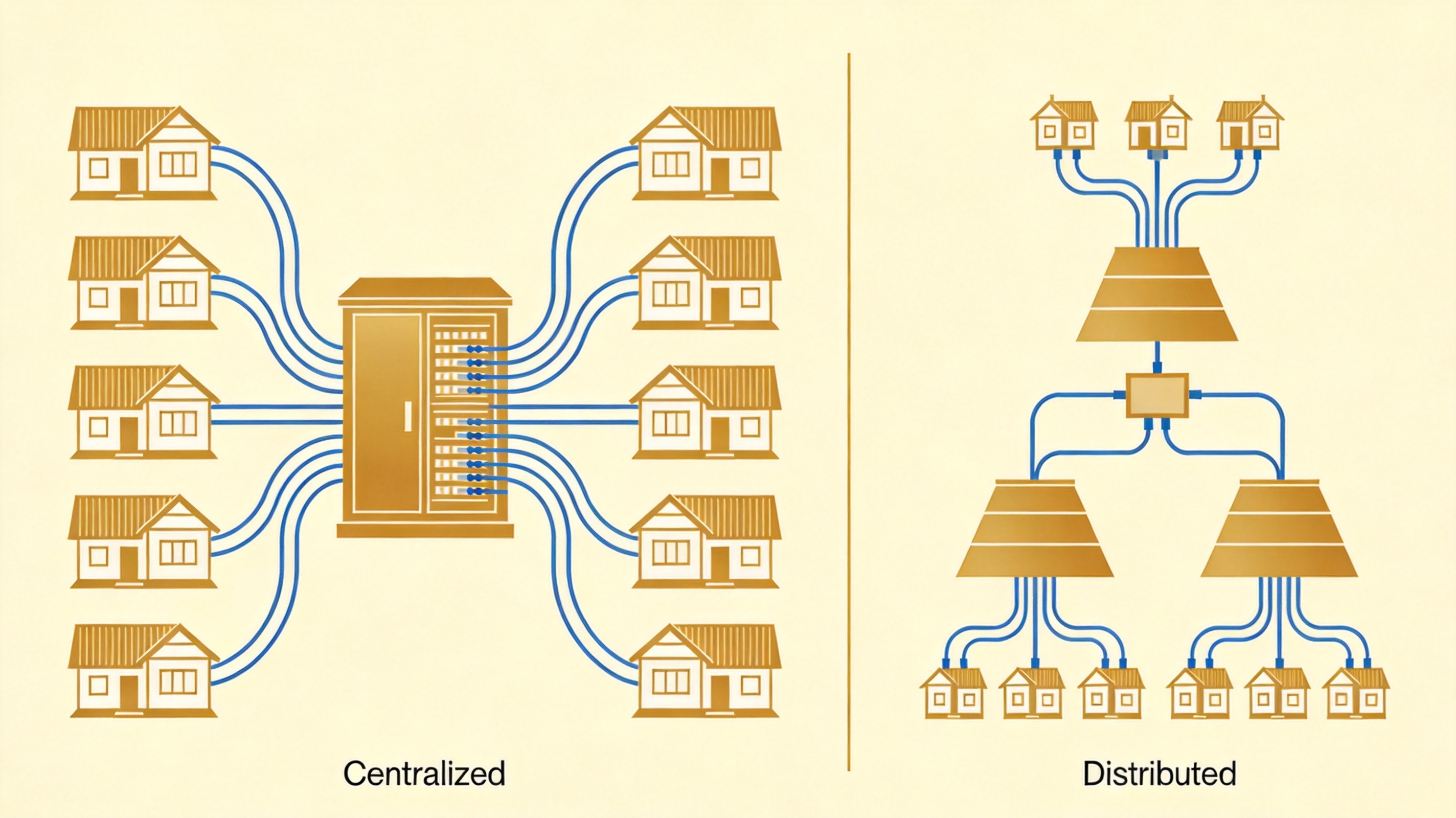
Centralized vs Distributed Splitting in PON
How splitting architecture affects your ODN.
Read Article → Fiber Optic Splitter Guide
The complete reference on fiber optic splitters.
Read Article →
FTTH Network Architecture
How an FTTH network is built end to end.
Read Article →